
Referring to the original material at ESP32 with DHT11/DHT22 Temperature and Humidity Sensor using Arduino IDE | Random Nerd Tutorials
The reference is straight forward; however, it is not for the esp32-wrover.
Based on the from the reference, using educated guess without reading the specification, it is a hindsight that the original wiring will not work.
It didn’t work, was getting the error “Failed to read from DHT sensor!” from the sample code.
DHTPIN were used is 4, which I had wrongly assumed it to be the physical pin number. Little did I know that, the reference is referring to GPIO4 instead of the physical pin number.
Based on the reference, ESP32-wrover spec sheet page 9, the physical pin 4 is the SENSOR_VP.
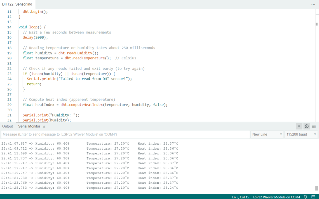
The sample code used were, this is the corrected code after discovering the spec sheet:
#include <DHT.h>
#define DHTPIN 13 // Digital pin connected to the DHT sensor
#define DHTTYPE DHT22 // DHT 22 (AM2302)
DHT dht(DHTPIN, DHTTYPE);
void setup() {
Serial.begin(115200);
Serial.println("DHT22 test!");
dht.begin();
}
void loop() {
// Wait a few seconds between measurements
delay(2000);
// Reading temperature or humidity takes about 250 milliseconds
float humidity = dht.readHumidity();
float temperature = dht.readTemperature(); // Celsius
// Check if any reads failed and exit early (to try again)
if (isnan(humidity) || isnan(temperature)) {
Serial.println("Failed to read from DHT sensor!");
return;
}
// Compute heat index (apparent temperature)
float heatIndex = dht.computeHeatIndex(temperature, humidity, false);
Serial.print("Humidity: ");
Serial.print(humidity);
Serial.print("%\t");
Serial.print("Temperature: ");
Serial.print(temperature);
Serial.print("°C\t");
Serial.print("Heat index: ");
Serial.print(heatIndex);
Serial.println("°C");
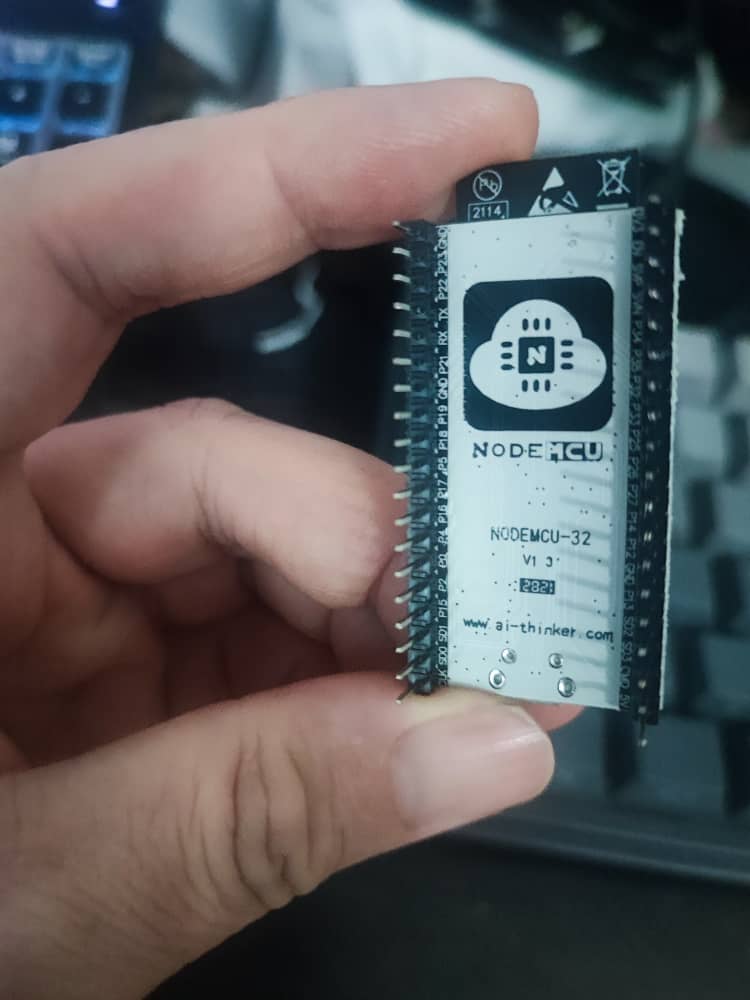
}Despite the reference to the spec sheet, apparently, the real IO13 is not reflected in the spec sheet. From the PCBA of the ESP32-Wrover-IE, the IO13 is not at the physical pin 16.
The printout on the PCBA shows IO13 is located on physical pin 15
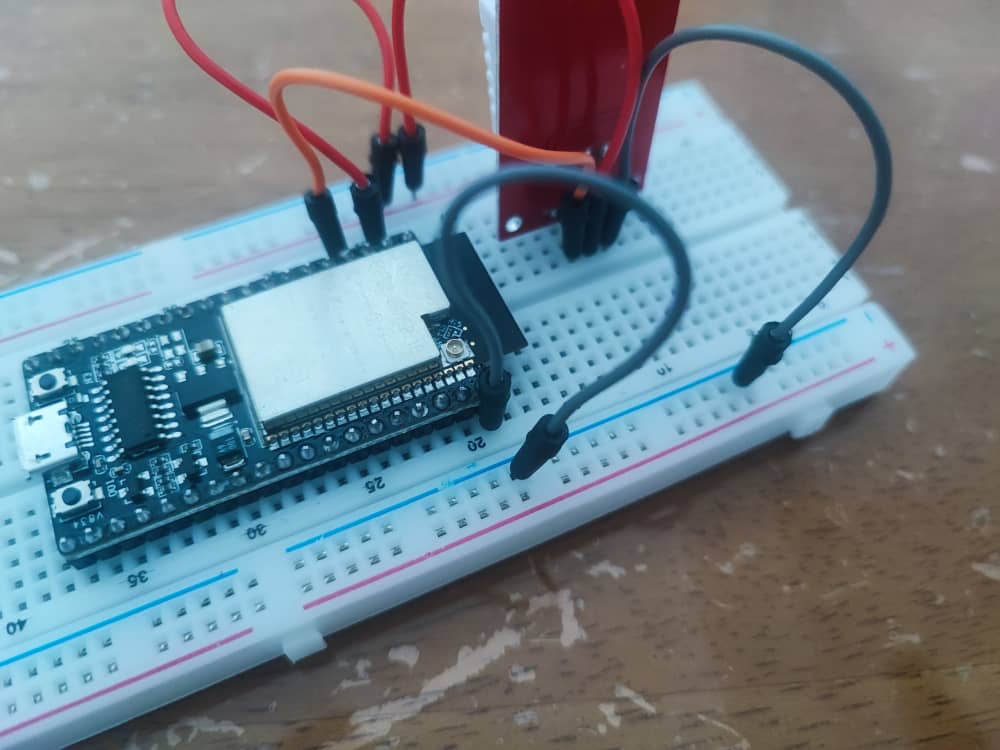
Despite wiring everything on the breadboard to the correct pin. The code still showing error.
Hence, the final resort was to remove the ESP32-wrover-ie from the breadboard and connecting the sensors directly using jumper cable directly to the ESP32-wrover board. Not elegant but it works fine.
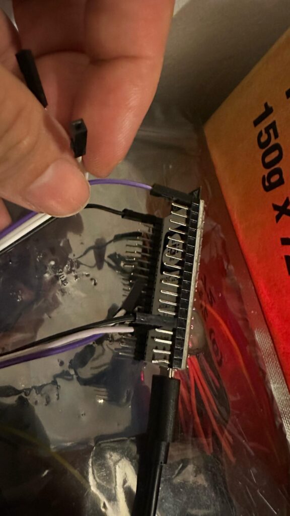
The final interfacing of DHT22 to ESP32-wrover was:
DHT22 VCC pin to connect to the ESP32-wrover physical pin 1, which will supply 3.3V.
DHT22 GND pin to connect to the ESP32-wrover physical pin 20, which is the ground.
Lastly, the DHT22 DAT pin to the ESP32-wrover physical pin 15, which is the digital IO13.
Lessons learned:
1. For a fast experiment use jumper cables to connect the pins directly.
2. Specification sheet may not match the actual product, refer to the PCBA for the latest IO.
3. Breadboard could be the reason why your sensor and your board are not connecting if your code is workable.
4. May need to consider buying a multi-function voltmeter to perform real hardware verification and validation.
What to be improved further, add ability to send data collected from DHT22 to an edge web service using Wi-Fi. Create a simple web service running REST API on a raspberry pi that will act as an edge web server to receive data.