
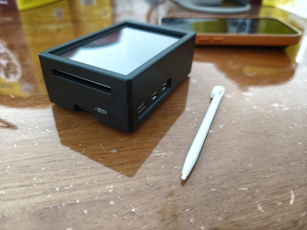
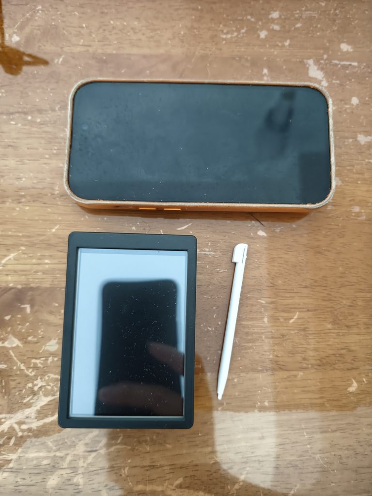
This is a relatively simple project; all the parts are off-the-shelf (OTS) or in simple language it can be procured or bought from any electronics store or webstore.
This project requires understanding of how to load Raspberry PI compliant OS and any PI OS that is compatible with driver of the 3.5″ touch screen LCD. Familarity to use command shell or terminal or SSH shell.
To start out, here are the list of components for the Raspberry PI 5 with 3.5″ resistive touch screen LCD.
Here are the lists of OTS components:
| CPN/MPN | Description | Supplier URL | Quantity | Cost |
| SC1432 | Raspberry Pi 5 Computer with 8GB RAM | https://my.cytron.io/p-raspberry-pi-5-with-8gb-ram | 1 | RM767.00 |
| BO-PI5-HAC-AL (Cytron Part Number) | Active Cooler for Raspberry Pi 5 – Black | https://my.cytron.io/p-active-cooler-for-raspberry-pi-5-black | 1 | RM24.90 |
| SC1154 | Raspberry Pi USB-C PD (Power Delivery) 27W PSU – UK – Black | https://my.cytron.io/p-raspberry-pi-usb-c-pd-power-delivery-27w-psu-uk-black | 1 | RM53.60 |
| DS-TFT-3.5 (Cytron Part Number) MPI3511 | 3.5 inch SPI/HDMI Touch Screen Display for Raspberry Pi | https://my.cytron.io/p-3.5-inch-tft-touch-screen-for-rpi-3b-3b-plus-4b | 1 | RM65.00 |
| BO-RPI5-3.5 (Cytron Part Number) | 3.5″ Touch Screen Case for Raspberry Pi 5 | https://my.cytron.io/p-3.5-touch-screen-case-for-raspberry-pi-5 | 1 | RM13.90 |
| 40-700967 (TechMakers Part Number) | Kapton Tape High temperature resistant tape for 3D printer platform | https://shop.techmakers.com.my/kapton-tape-high-temperature-resistant-tape-for-3d-printer-platform | 1 | RM8.90 |
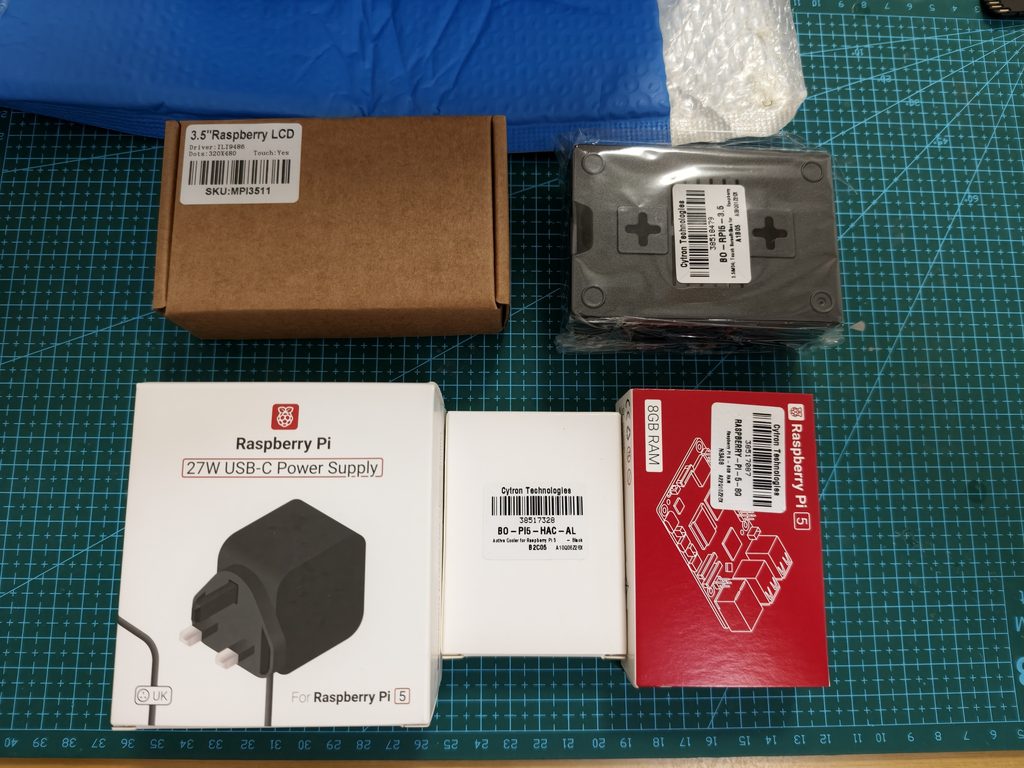
First thing first, always power on to test the most expensive component, in this case the Raspberry PI 5.
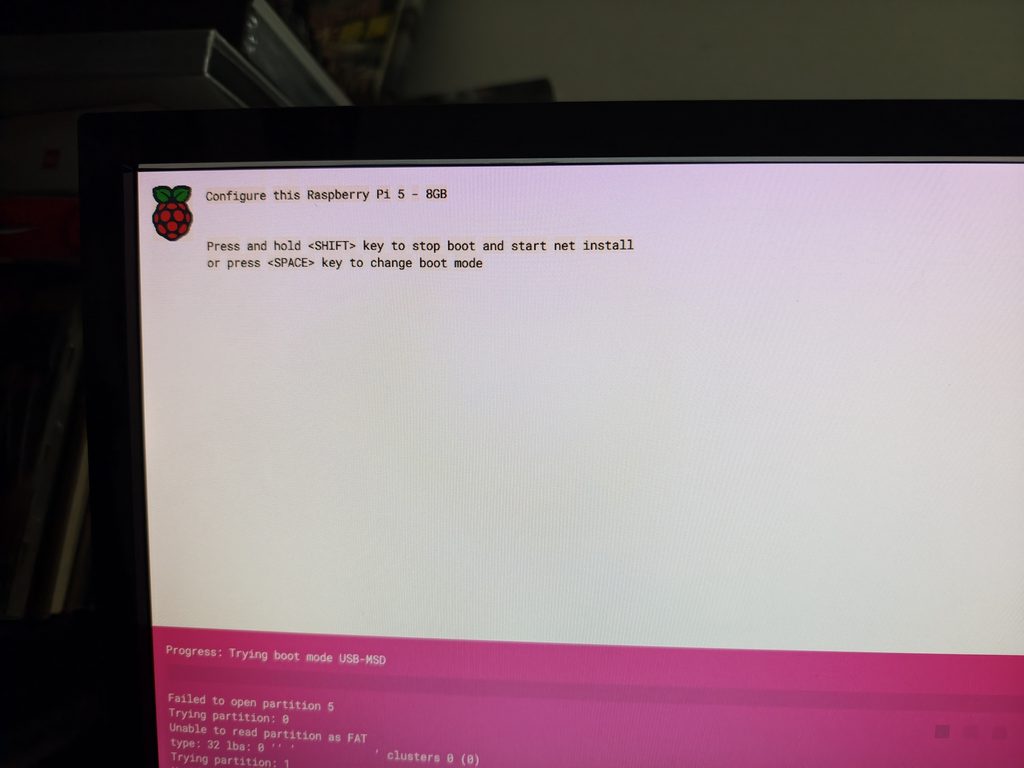
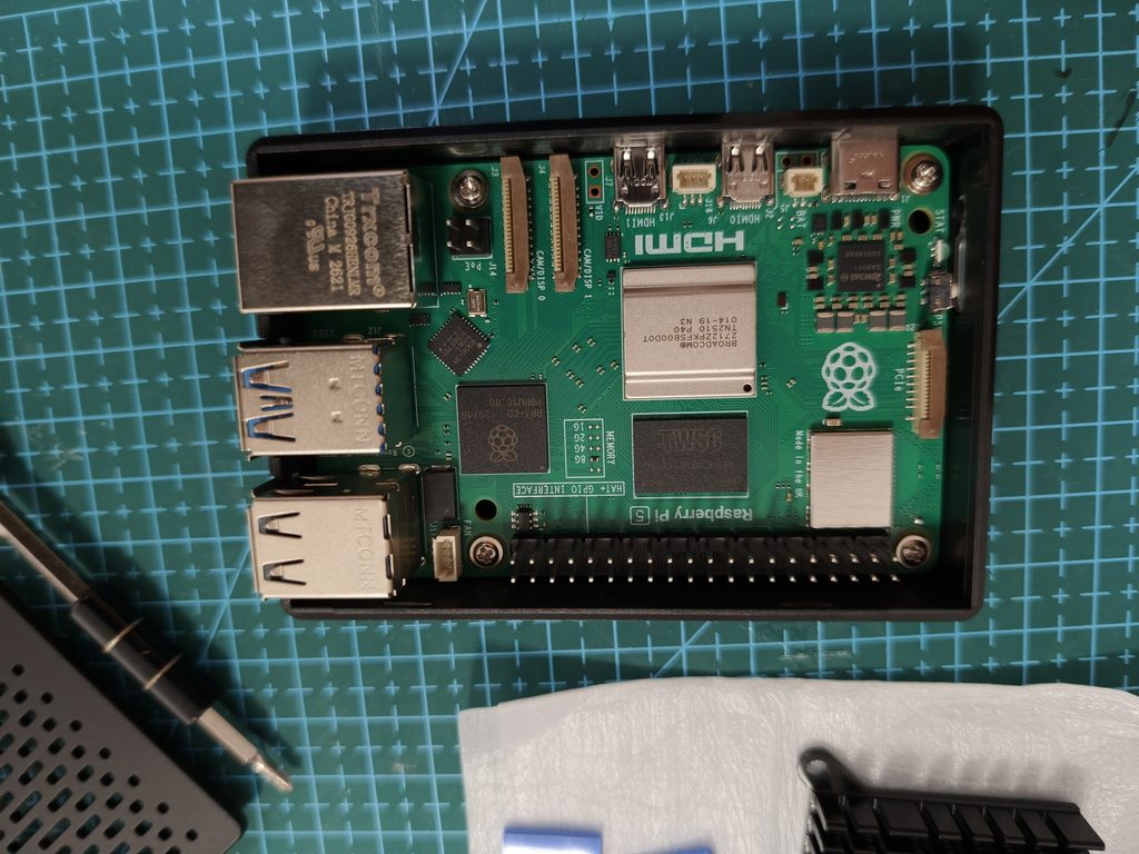
Quick view of the Raspberry PI 5.
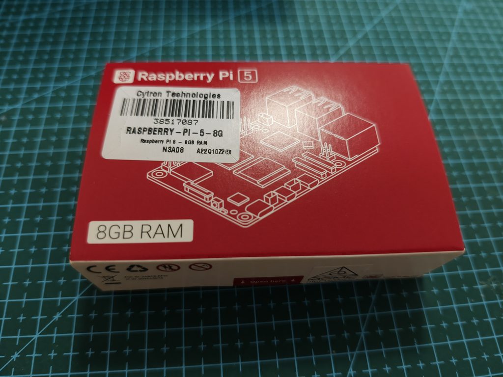
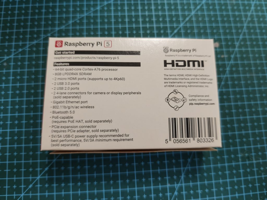
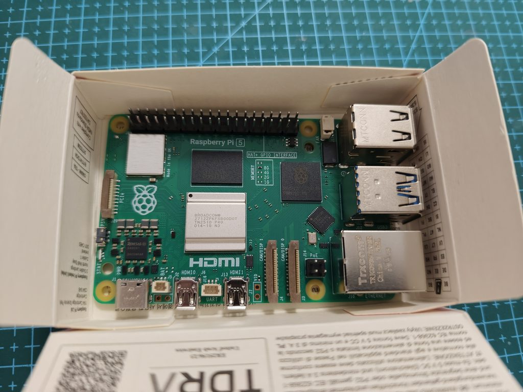
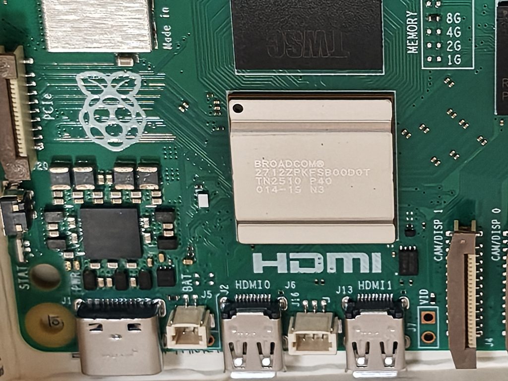
Broadcom 2712ZPKFSB00D0T SoC used as the heart of Raspberry PI 5, I suspect the TN2510 and others are the “birth certificate” of the respective chip.
The board has a resistor fused at 8GB, which means this is a Raspberry PI 8GB.
Using Gemini AI to analyze this image here are some interesting facts not verified. Will need Broadcom folks to confirm.
Breakdown of the Codes in the chip according to Gemini AI:
Line 1 BROADCOM®: The registered trademark of the fabless semiconductor company that designed the processor.

Line 2 2712ZPKFSB00D0T:
• 2712: The SoC model number (BCM2712).
• ZPKFSB00: Internal packaging, ball grid array layout configuration, and thermal/environmental spec identifiers.
• D0: The silicon stepping version indicating an optimized, refined fabrication revision.
• T: Tape-and-reel or operational temperature rating indicator code.

Line 3 TN2510 P40:
• TN: Code representing the specific contract semiconductor foundry or packaging facility location where the chip was encapsulated.
• 2510: The manufacturing date code indicating the year and week of production. 2510 implies the chip was packaged in the 10th week of 2025 (early March 2025).
• P40: Internal Broadcom tracking index identifying the assembly production line or target test platform qualification group.

Line 4 014-19 N3:
• 014-19: The batch processing identifier or unique production lot tracking sub-number.
• N3: Refers to a matrix position index tracking which specific silicon wafer or quadrant coordinate zone the die originated from inside the manufacturing foundry.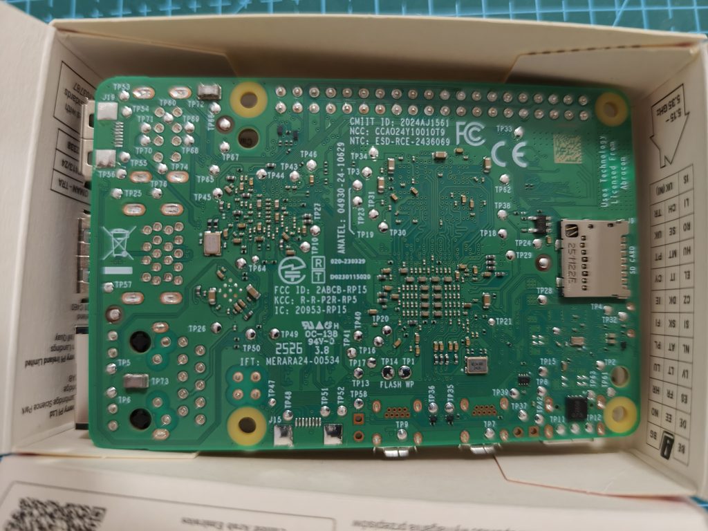
Check the enclosure meant to be housing the entire project.
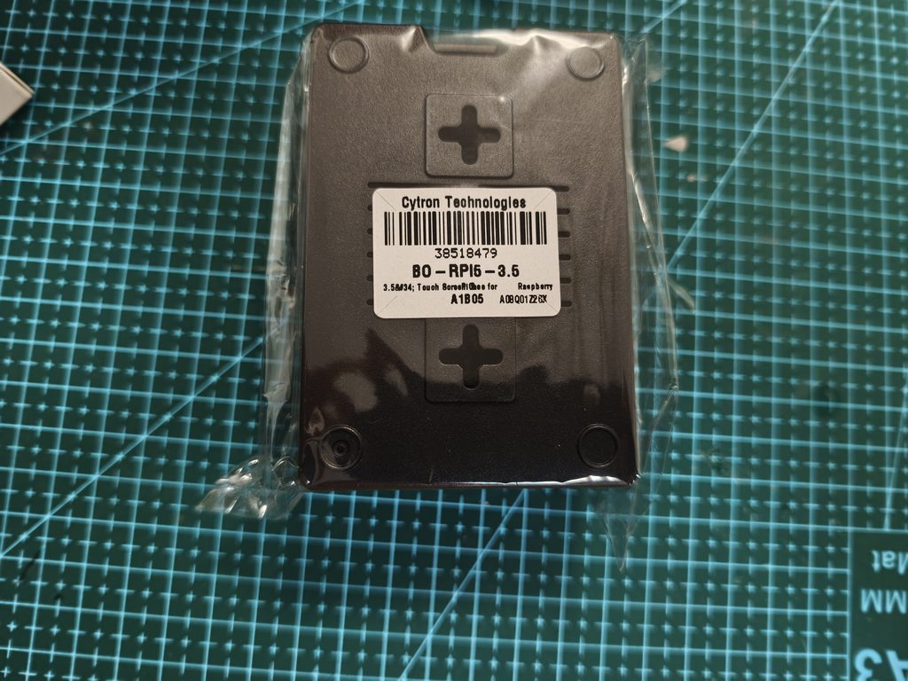
This enclosure detailed description on the Cytron website describe the enclosure to be able to enclose Raspberry PI 5 with the 3.5″ resistive touch screen. On inspection of eyeball and touch, its a good quality enclosure, no sign it is a 3D printed enclosure. Hence, it will be a solid enclosure to house both Raspberry PI 5 with the 3.5″ resistive touch LCD.
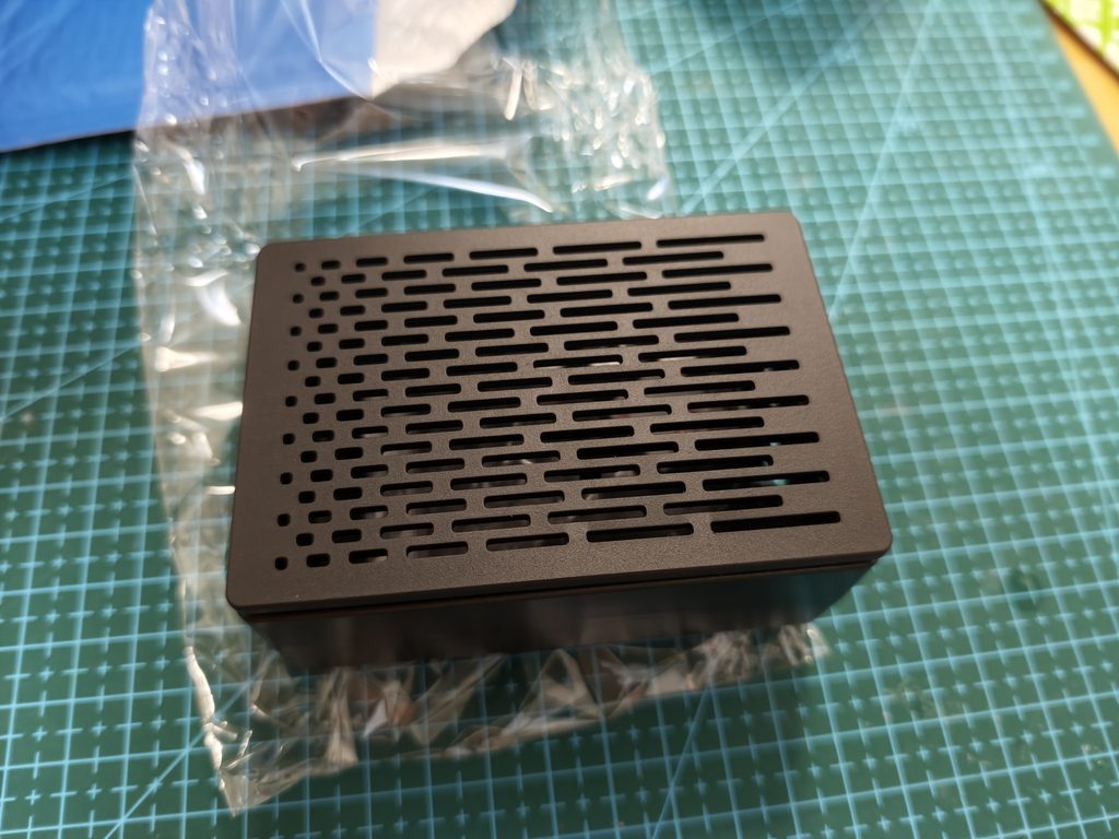
The enclosure does work for Raspberry PI 5 without LCD as an alternative cover is included.
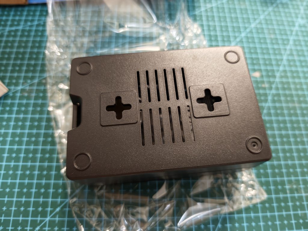
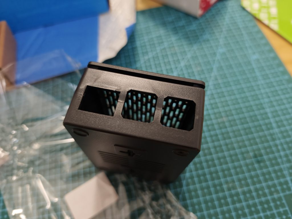
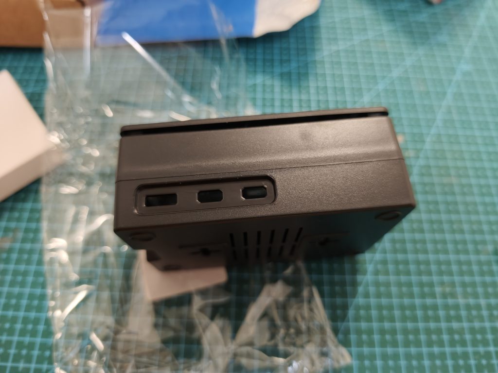
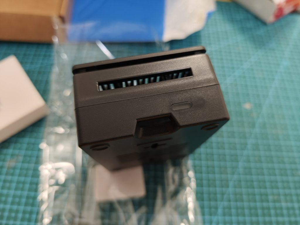
A well-designed enclosure. mounting the Raspberry PI 5 is easy, and 4 included to ensure the Raspberry PI is mounted securely on the enclosure.
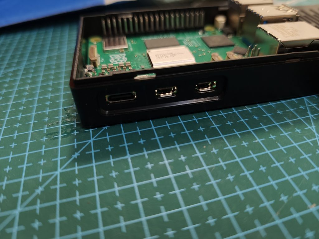
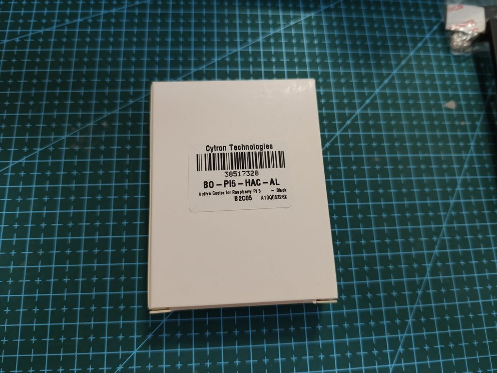
Next the active cooler. It comes in a very generic box.
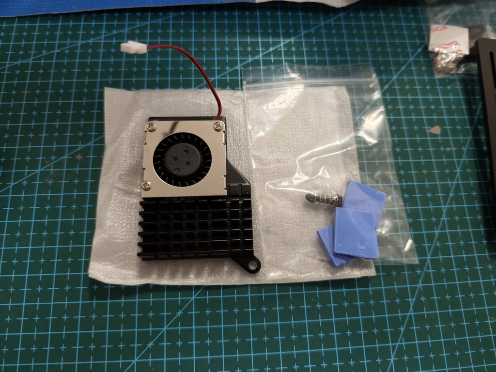
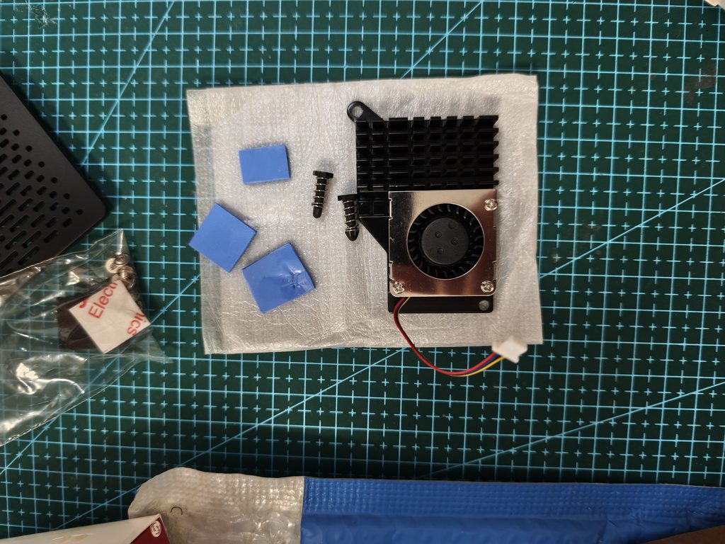
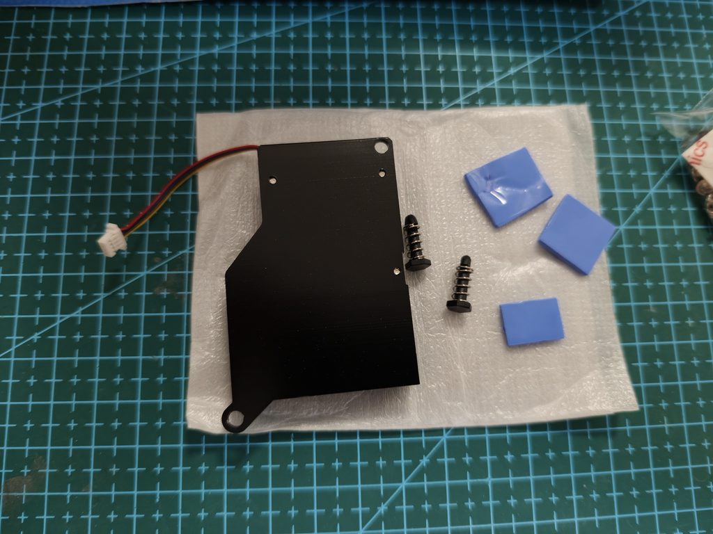
Even before physically mount the active cooler, the appearance of the active heat sink is a very low-profile.
To proceed to mount the active heat sink, first put the thermal pads on the chips, make sure the protection tape of the themal pads are remove one side first. Remove the other protection pad when satistfied of the position.
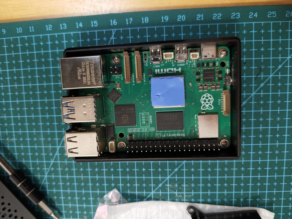
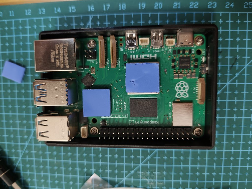
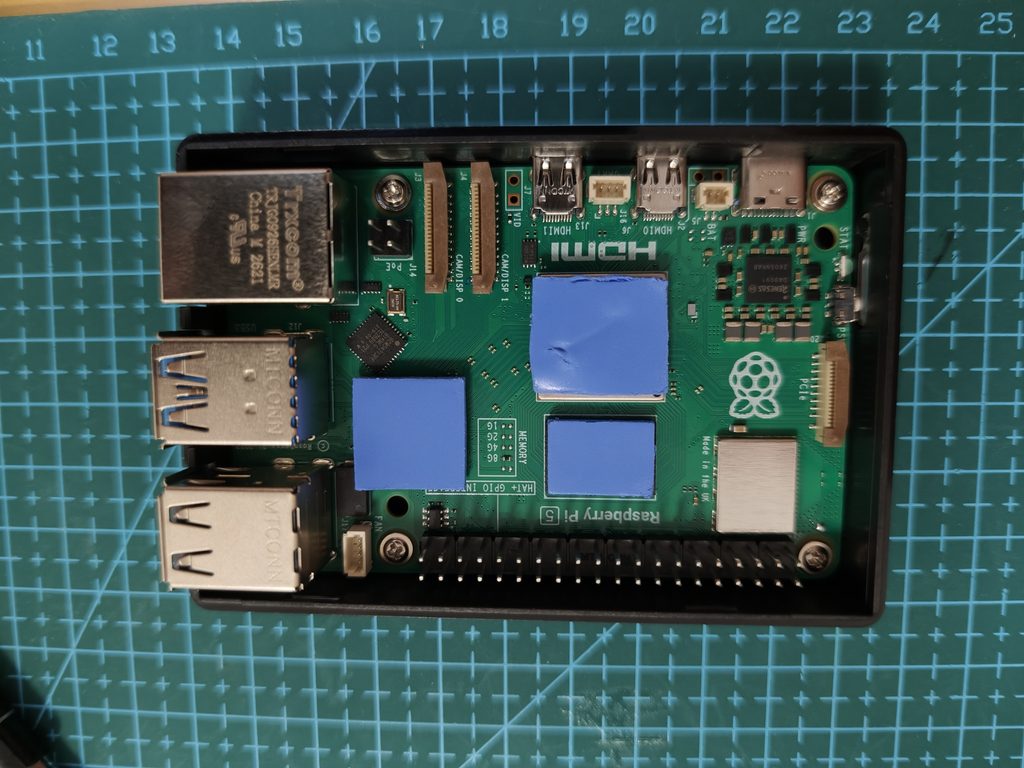
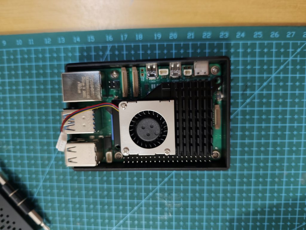
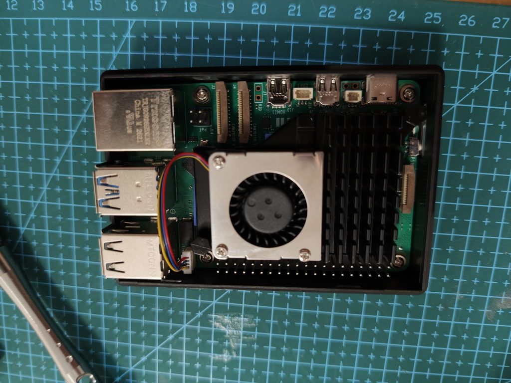
Despite the power cable is easy, make sure the yellow cable is next to the enclosure and red cable is the cable facing the board.
To ensure things work power on, this part is assuming a Raspberry PI 5 OS is successfully install and booted once.
Most of the default OS for Raspberry PI 5, the fan do not activate.
Add the following into /boot/firmware/config.txt
# Enable cooling fan (if previously disabled or unrecognized)
dtparam=cooling_fan=on

# Level 1: Start at 45°C, speed 75 (approx. 30%), reduce speed when temperature drops to 40°C
dtparam=fan_temp0=45000
dtparam=fan_temp0_hyst=5000
dtparam=fan_temp0_speed=75

# Level 2: 55°C, speed 128 (approx. 50%)
dtparam=fan_temp1=55000
dtparam=fan_temp1_hyst=5000
dtparam=fan_temp1_speed=128

# Level 3: 65°C, speed 192 (approx. 75%)
dtparam=fan_temp2=65000
dtparam=fan_temp2_hyst=5000
dtparam=fan_temp2_speed=192

# Level 4: 75°C, full speed 255
dtparam=fan_temp3=75000
dtparam=fan_temp3_hyst=5000
dtparam=fan_temp3_speed=255
After modifying the /boot/firmware/config.txt save it and reboot the raspberry PI.
Upon rebooting during boot up the active heat sink fan will start to spin.
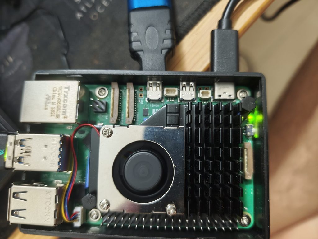
This is the part of installing the driver for the LCD into your Raspberry PI OS.
Make sure the SSH server is installed, as I am installing the driver using command line via a PuTTy client.
This is presuming also you have linux understanding and did all updates and have installed git client.
Use your other computer to visit the driver page at GitHub – goodtft/LCD-show: 2.4″ 2.8″3.2″ 3.5″ 5.0″ 7.0″ TFT LCD driver for the Raspberry PI 3B+/A/A+/B/B+/PI2/ PI3/ZERO/ZERO W · GitHub
Then read this README markup from the github site LCD-show/README.md at master · goodtft/LCD-show · GitHub

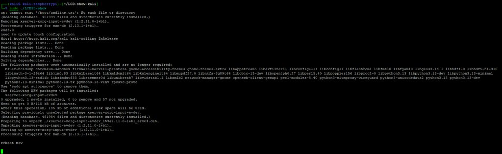
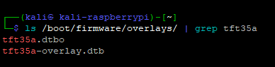
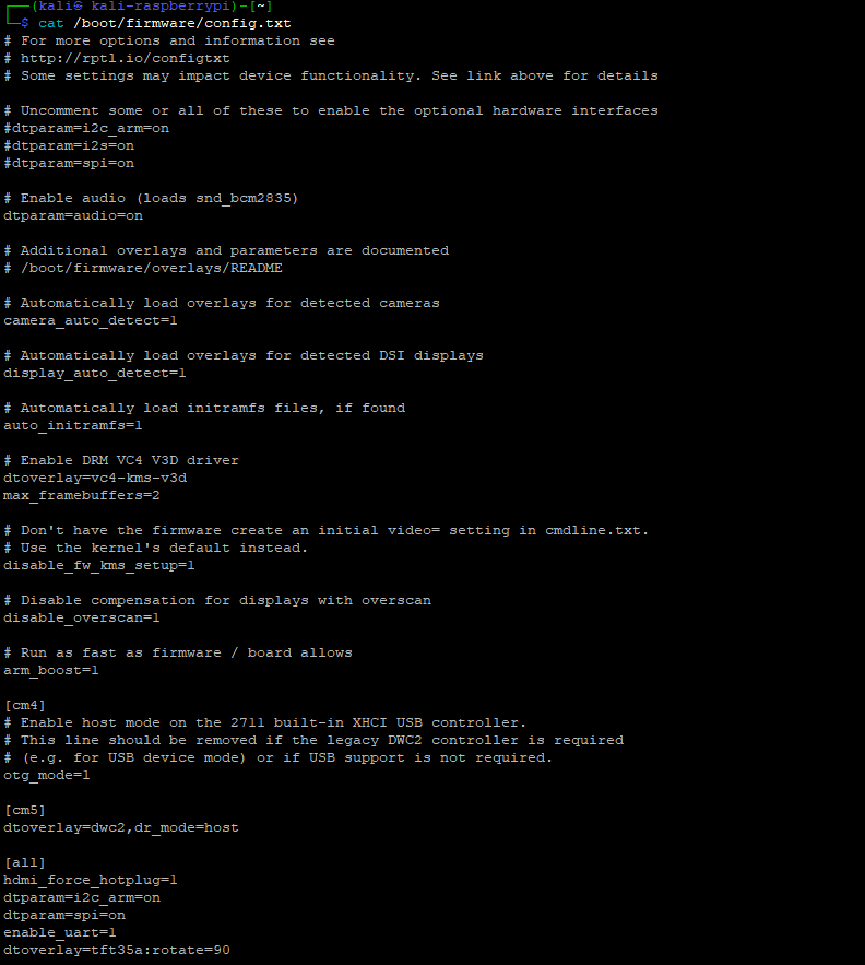
Power down your raspberry PI.
Make sure that your raspberry PI 5 is fully powered down, detached power supply from your Raspberry PI before proceed next step.
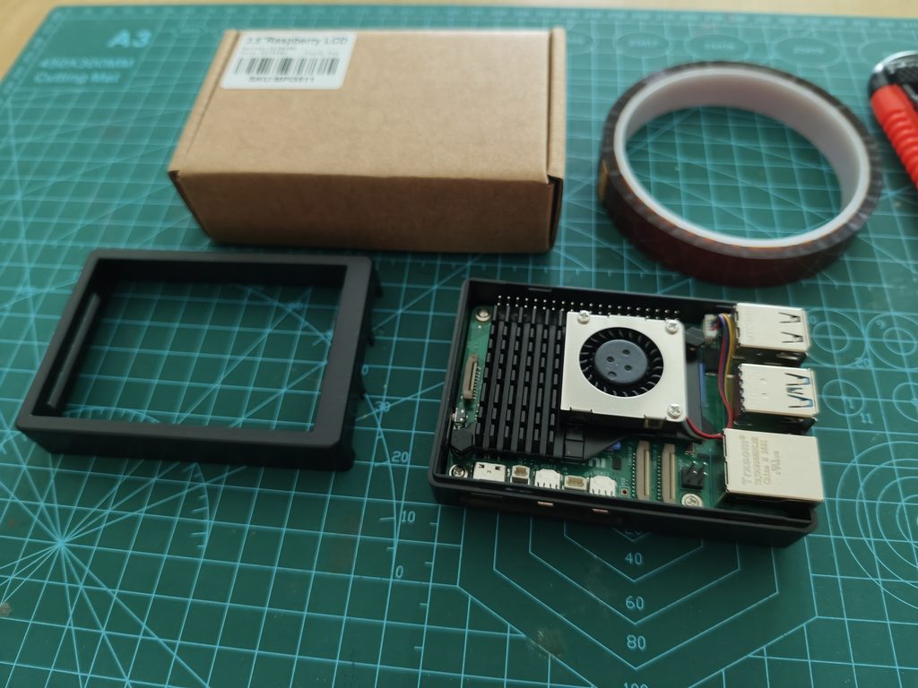
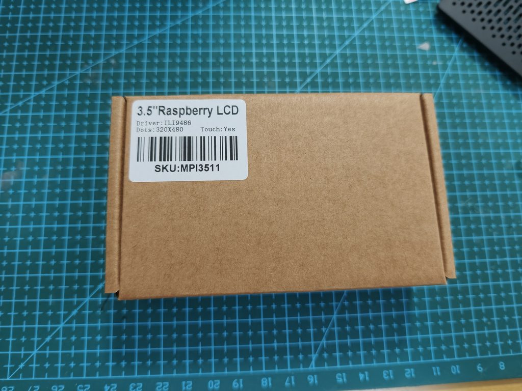
This is just on time to review the 3.5″ resistive touch LCD.
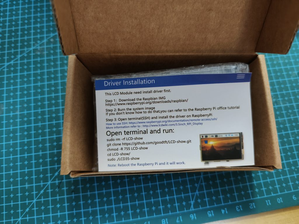
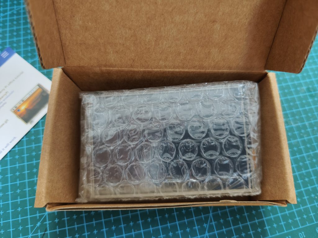
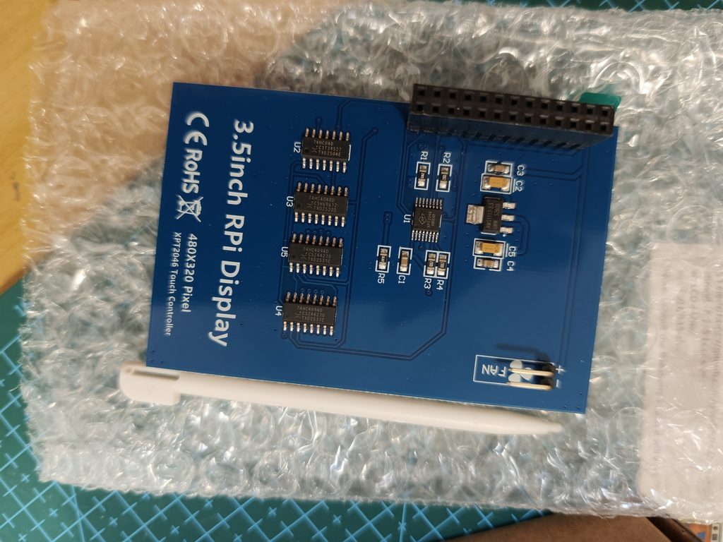
This exposed IC under the LCD are the main reason for buying a Kapton tape that is 15mm width.
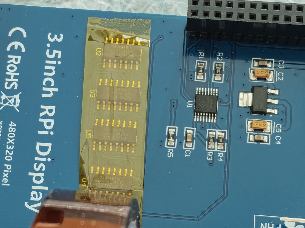
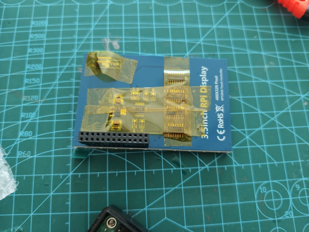
Kapton tape has 2 functions, to act as heat and electrical touch insulators. As the gap between active heat sink and the ICs of LCD are too close.
Then install the LCD to the Raspberry PI 5. Make sure the pin are correct and there is no gap in between the connectors.
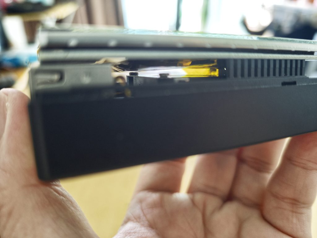
Before closing the enclosure, make a power on test. Do not worry if the LCD is white or black, it will take a while for the OS to load correct driver before the Raspberry OS kernel loading is shown.
The reason there is no standard Raspberry POST that shows the White Pink boot up, this is due to the LCD interface is SPI. SPI is at a lower boot order than native HDMI Interface.
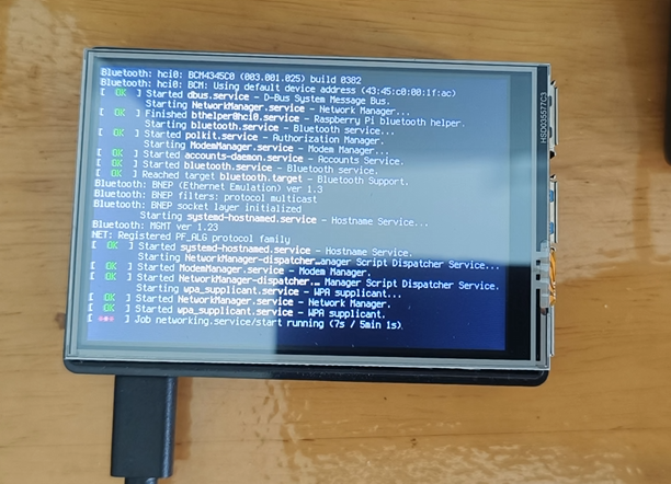
If there is blank screen for a long time, do not worry it may need more tweak especially you are not using OS that is supported by the LCD driver. Best fix will be just using the OS recommended by the LCD manufacturer.
If you are successful to load with LCD showing the login screen. Shutdown and power down. Time to complete the installation of the enclosure.
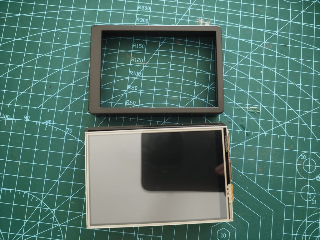
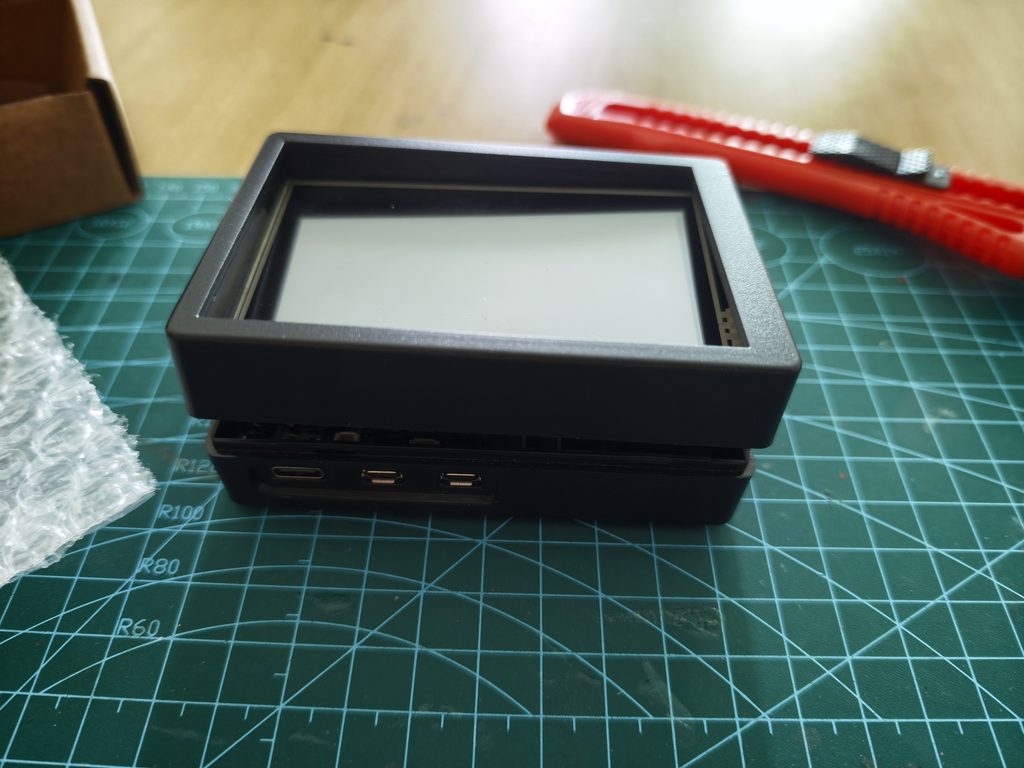
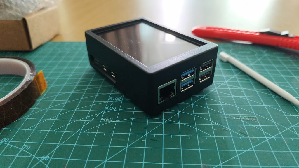
With the 2nd half of the enclosure fit snuggly. The installation of 3.5″ resistive touch LCD to Raspberry PI 5 is completed.
The installation of this setup is easy for me. For full transparency the real roadblock that i had faced is surprised by the exposed IC. Initial installation of the LCD which has a very tiny gap is disturbing to me. Hence, the solution discovered was using Kapton tape to mask the exposed LCD ICs. The hurdle of choosing Kapton tape take half a day as the expensive Polymide tape was first discovered, a roll of it will cost RM170+.
Thanks to AI like DeepSeek to source a cheaper alternative is just a simple prompt of asking what is the alternative to polymide as i feel it is sunken cost fallacy to spend RM170+ to complete a RM930+ project.
Conclusion, this project is made easy due to far progress of technology better component at relatively cheap price, and it is all off-the-shelf (OTS). Having AI assistant, it can at as an advanced sourcing agent. So, this is an easy project to be completed.