Next, generate the certificates that are needed by Wazuh to work. Make sure to decide to run on a single node or multinode indexer Wazuh. Go to the appropriate directory from the cloned Wazuh git repo. Then run
sudo docker-compose -f generate-indexer-certs.yml run --rm generator
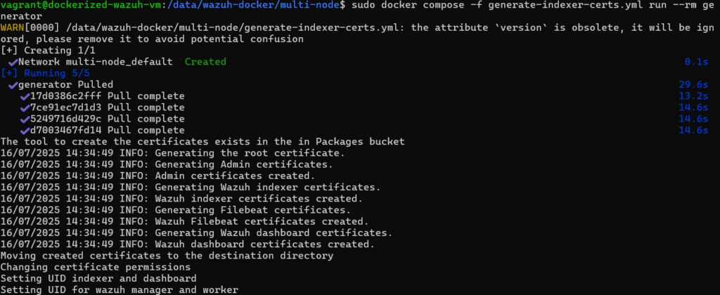
If you are using the newer version aka Version 2 docker compose run the following instead
sudo docker compose -f generate-indexer-certs.yml run --rm generator
Once certificate are generated correctly
Once the certificate is installed, go to the correct directory then run the following:
sudo docker-compose up -d
Again, should version 2 of docker compose is used run the following instead
sudo docker compose up -d
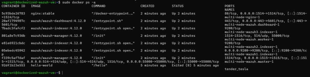
Wazuh multinode when running correctly
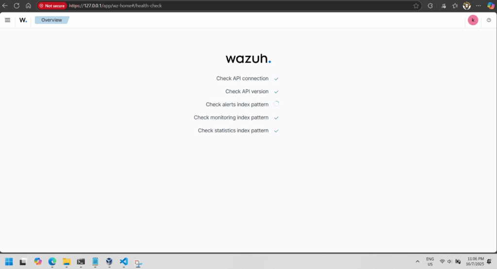
If everything is good you will be able to browse to your Wazuh dashboard in a minute or 2.
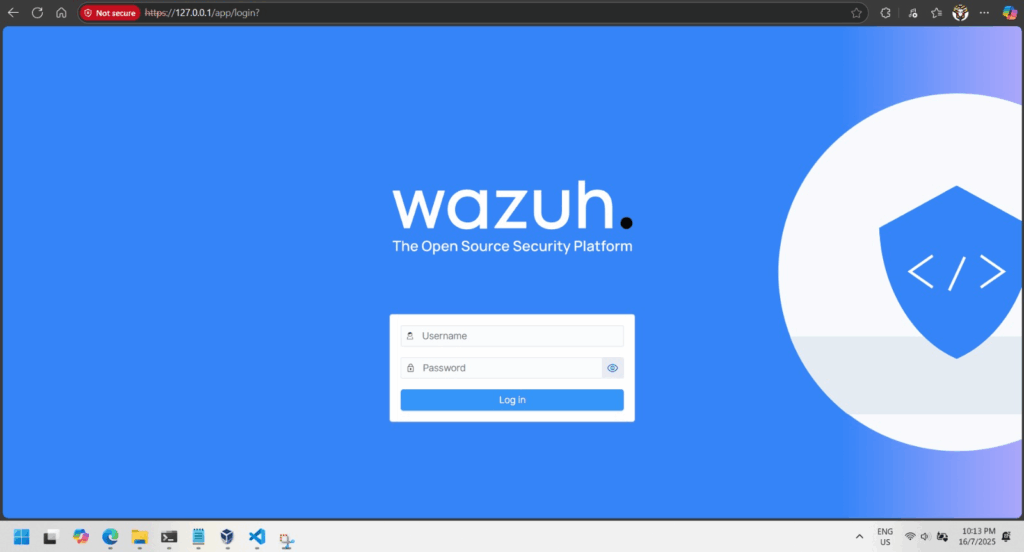
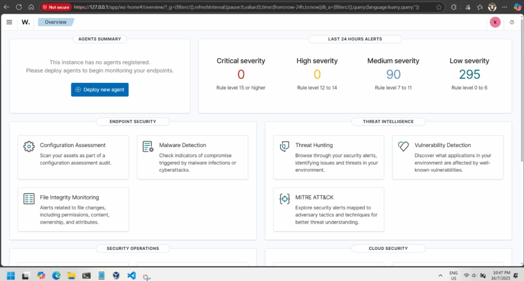
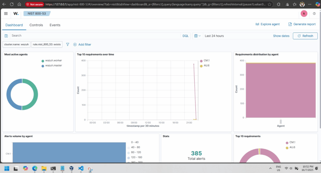
Wazuh dashboard loginFirst time login into Wazuh dashboardWazuh Dashboard overviewSecurity warning or violation visualized
Wazuh SIEM (Security Information and Event Management) platform can help protect systems.
Wazuh SIEM Solution
Wazuh is a free, open-source tool that monitors systems, detects attacks, and logs security events.
It consists of:
Wazuh Server (collects and analyzes logs).
Wazuh Agents (installed on devices to send logs).
Wazuh Dashboard (visualizes threats and alerts).
Simulated Attacks & Findings
Brute Force Attacks: Hackers try guessing passwords repeatedly. Wazuh detects and blocks these attempts.
SQL Injection: Hackers inject malicious code into websites. Wazuh logs and prevents unauthorized access.
Shellshock Attack: Exploits a Linux vulnerability. Wazuh identifies and stops such attempts.
Security Recommendations
Regularly update software to fix vulnerabilities.
Use strong passwords and multi-factor authentication.
Monitor systems with tools like Wazuh to detect threats early.
Conclusion Wazuh helps organizations detect, analyze, and respond to cyber threats before they cause harm. By implementing strong security measures, users can protect their systems from the dangers of the “Wild Web.”
Final Thought: Cybersecurity is essential—tools like Wazuh make it easier to stay safe online!
The reference is straight forward; however, it is not for the esp32-wrover.
Based on the from the reference, using educated guess without reading the specification, it is a hindsight that the original wiring will not work.
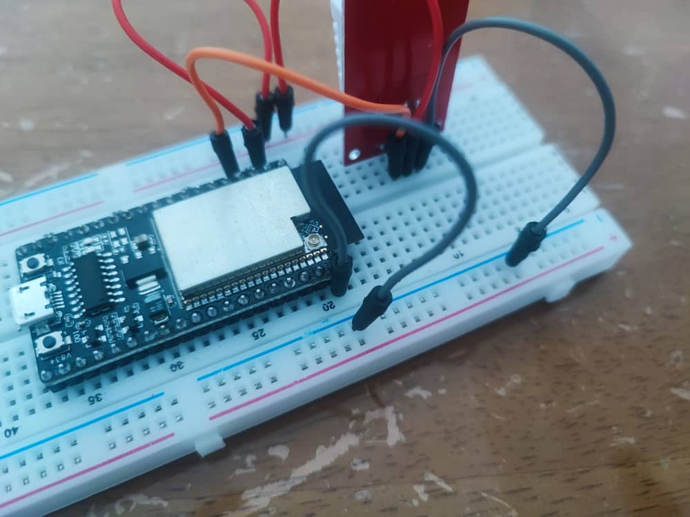
Original wiring on the breadboard for the ESP32-wrover, spoiler this is wrong for many reasons
It didn’t work, was getting the error “Failed to read from DHT sensor!” from the sample code.
DHTPIN were used is 4, which I had wrongly assumed it to be the physical pin number. Little did I know that, the reference is referring to GPIO4 instead of the physical pin number.
Based on the reference, ESP32-wrover spec sheet page 9, the physical pin 4 is the SENSOR_VP.
The hardest part is to determine what are the connector chip and installing libraries into Arduino IDE. Refer to the shared link in the beginning of this post.
Code from DeepSeek for a complicated hello world, assuming to make the LED blinks in morse code:
#include <Arduino.h>

#define LED_PIN 2  // Built-in LED on GPIO 2

// Morse code representations for A-Z
const char* morseCodes[] = {
  ".-",    // A
  "-...",  // B
  "-.-.",  // C
  "-..",   // D
  ".",     // E
  "..-.",  // F
  "--.",   // G
  "....",  // H
  "..",    // I
  ".---",  // J
  "-.-",   // K
  ".-..",  // L
  "--",    // M
  "-.",    // N
  "---",   // O
  ".--.",  // P
  "--.-",  // Q
  ".-.",   // R
  "...",   // S
  "-",     // T
  "..-",   // U
  "...-",  // V
  ".--",   // W
  "-..-",  // X
  "-.--",  // Y
  "--.."   // Z
};

void setup() {
  pinMode(LED_PIN, OUTPUT);  // Set the LED pin as an output
  Serial.begin(115200);
}

void loop() {
  String message = "SOS";  // Message to transmit in Morse code
  message.toUpperCase();   // Convert message to uppercase

  // Transmit the message in Morse code
  for (int i = 0; i < message.length(); i++) {
    char currentChar = message[i];
    if (currentChar >= 'A' && currentChar <= 'Z') {
      transmitMorse(morseCodes[currentChar - 'A']);  // Transmit Morse code for the character
    } else if (currentChar == ' ') {
      delay(1400);  // Gap between words (7 units)
    }
    delay(600);  // Gap between letters (3 units)
  }

  delay(2000);  // Wait before repeating the message
}

// Function to transmit a Morse code pattern
void transmitMorse(const char* morseCode) {
  for (int i = 0; i < strlen(morseCode); i++) {
    if (morseCode[i] == '.') {
      blinkDot();  // Transmit a dot
    } else if (morseCode[i] == '-') {
      blinkDash();  // Transmit a dash
    }
    delay(200);  // Gap between dots/dashes (1 unit)
  }
}

// Function to blink a dot (short flash)
void blinkDot() {
  digitalWrite(LED_PIN, HIGH);  // Turn the LED on
  delay(200);                   // Dot duration (1 unit)
  digitalWrite(LED_PIN, LOW);   // Turn the LED off
}

// Function to blink a dash (long flash)
void blinkDash() {
  digitalWrite(LED_PIN, HIGH);  // Turn the LED on
  delay(600);                   // Dash duration (3 units)
  digitalWrite(LED_PIN, LOW);   // Turn the LED off
}
Code to connect to WiFi:
#include <WiFi.h>

// Replace with your network credentials
const char* ssid = "myhome4iot";
const char* password = "i have the longest wifi password ever";

void setup() {
  Serial.begin(115200);

  // Connect to Wi-Fi
  WiFi.begin(ssid, password);
  Serial.println("Connecting to Wi-Fi...");

  // Wait for connection
  while (WiFi.status() != WL_CONNECTED) {
    delay(1000);
    Serial.print(".");
  }

  // Connection successful
  Serial.println("\nWi-Fi connected!");

  // Get and print network information
  IPAddress ip = WiFi.localIP();
  IPAddress gateway = WiFi.gatewayIP();
  IPAddress dns = WiFi.dnsIP();

  Serial.println("Network Information:");
  Serial.print("IP Address: ");
  Serial.println(ip);
  Serial.print("Gateway: ");
  Serial.println(gateway);
  Serial.print("DNS Server: ");
  Serial.println(dns);
}

void loop() {
  // Nothing to do here
}
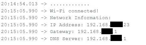
Returning IP information of ESP32
Code to scan WiFi:
#include <WiFi.h>

void setup() {
  Serial.begin(115200);

  // Set ESP32 to station mode
  WiFi.mode(WIFI_STA);
  WiFi.disconnect();  // Disconnect from any previous connection
  delay(100);

  Serial.println("Starting Wi-Fi scan...");
}

void loop() {
  // Scan for nearby Wi-Fi networks
  int numNetworks = WiFi.scanNetworks();

  if (numNetworks == 0) {
    Serial.println("No networks found.");
  } else {
    Serial.print(numNetworks);
    Serial.println(" networks found:");
    for (int i = 0; i < numNetworks; i++) {
      // Print SSID and RSSI for each network
      Serial.print(i + 1);
      Serial.print(": ");
      Serial.print(WiFi.SSID(i));  // SSID
      Serial.print(" (");
      Serial.print(WiFi.RSSI(i));  // Signal strength (RSSI)
      Serial.print(" dBm)");
      Serial.print(" [");
      Serial.print(getEncryptionType(WiFi.encryptionType(i)));  // Encryption type
      Serial.println("]");
    }
  }

  Serial.println("-----------------------------");
  delay(10000);  // Wait 10 seconds before scanning again
}

// Function to convert encryption type to a human-readable string
String getEncryptionType(wifi_auth_mode_t encryptionType) {
  switch (encryptionType) {
    case WIFI_AUTH_OPEN:
      return "Open";
    case WIFI_AUTH_WEP:
      return "WEP";
    case WIFI_AUTH_WPA_PSK:
      return "WPA";
    case WIFI_AUTH_WPA2_PSK:
      return "WPA2";
    case WIFI_AUTH_WPA_WPA2_PSK:
      return "WPA/WPA2";
    case WIFI_AUTH_WPA2_ENTERPRISE:
      return "WPA2 Enterprise";
    case WIFI_AUTH_WPA3_PSK:
      return "WPA3";
    case WIFI_AUTH_WPA2_WPA3_PSK:
      return "WPA2/WPA3";
    default:
      return "Unknown";
  }
}
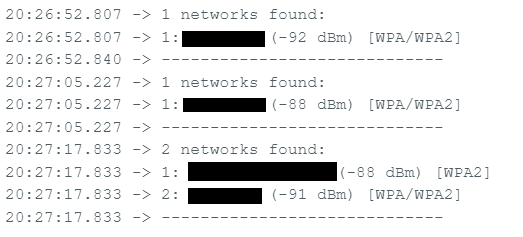
Unfortunately, due to the ESP32-WROVER hardware limitation, any modern 5GHz WiFi will not be able to be scanned or detected. On top of that, the stock ESP32-WROVER-IE needs to have a actual wifi cable to extend its range.
WiFi range is too short to scan a large area as well as limitation of WiFi hardware/chip